Wheel Offset & Tyre Diameter Calculator
Wheel offset is the ET value marked on a wheel, such as +45 or ET45.
Load original sizes from a vehicle, or enter the current and replacement dimensions manually.
What this calculator can do
- Enter current and replacement wheel spacer thicknesses in mm; their difference is included in inward and outward movement.
- Set and retain front and rear wheel, tyre and spacer dimensions independently, including staggered sizes.
- Compare current and replacement wheel and tyre positions in an SVG cross-section that updates with the inputs.
- Fixed structural diagrams explain rim-width, offset and clearance measurement references. These illustrations do not change with the inputs.

Selected vehicle: 日産 セレナ FPC26 ハイウェイスター Sエディション (2WD, CVT) · 2015/11–2016/08
Selected vehicle's original size (Both axles)
195/65R15 / 15x5.5J +45
Frontis being edited. Front and rear settings are retained separately.
Even loaded original values may differ from a modified vehicle. Check the current setup against the actual installed dimensions, and compare staggered front/rear tyres separately.
Current wheel and tyre
15×5.5J / ET45·195/65R15Wheel Spacer 0mm / camber 0°
Wheel
Tyre and spacer
More settings and input options
Camber angle 0.0°
−10° to +10°. Negative angles tilt the top towards the vehicle. A blank input is treated as 0°.
Enter a complete size string
Replacement wheel and tyre
Wheel
Tyre and spacer
More settings and input options
Quick settings and presets
The +1/+2 inch presets choose a tyre with a similar diameter and a wheel whose outer edge stays close to the original position, with less than 10 mm additional inward movement.
Camber angle 0.0°
−10° to +10°. Negative angles tilt the top towards the vehicle. A blank input is treated as 0°.
Enter a complete size string
Calculate offset from a target position
Outer edge unchanged
Inner clearance unchanged
This is movement from the current rim position, not the remaining clearance.Positions are compared at 0° camber. Actual inner clearance is unknown; inspect the vehicle for interference and fitment.
Cross-section
Front: 独立懸架ストラット式
- Current
- Replacement
- Fender
- The wheel and tyre are approximate sections based on the entered dimensions. The vertical dashed line marks the hub mounting face.Suspension drawings are generic references. Brake and knuckle angles follow replacement camber. Drawn gaps do not represent actual clearances or establish fitment.
- Current rim width / offset
- 5.5 in / +45.0mm
- Replacement rim width / offset
- 5.5 in / +45.0mm
- Outer rim-edge movement
- Outer edge unchanged
- Inner rim-edge movement
- Inner edge unchanged
- Tyre diameter difference
- ±0.0mm
Rim width describes the tyre-supporting width. Offset is the distance from its centre to the mounting face. Increasing width extends both edges; changing offset shifts the whole assembly. Movement also includes the spacer-thickness difference.
Rim width, offset and worked example
Vehicle side is left; outside is right. The grey dashed line is rim centre and the blue dashed line is the hub mounting face. Rim width is not overall flange-to-flange width. This schematic is not drawn to a constant scale.
Example: from 6 inches / +45 mm to 7 inches / +48 mm, half the width increase is 12.7 mm. The outer edge moves out by 12.7−3 = 9.7 mm; the inner edge moves towards the vehicle by 12.7+3 = 15.7 mm. This hypothetical example has no spacers and 0° camber.
- Ride-height change from tyre diameter
- ±0.0mm
- Change in gap above tyre
- ±0.0mm
Positive values mean higher ride height or a larger gap; negative means lower or smaller. This estimate uses half the diameter difference at 0° camber with unchanged suspension settings, without tyre deflection under load.
Upper-edge position with camber
Upper-edge position with camber
Current 0.0° → replacement 0.0°
- Movement of upper outer point
- ±0.0mm
- Horizontal upper-edge distance to fender
- 20.3mm
- Vertical upper-edge distance to fender
- 30.3mm
This reference rotates the section about the hub centre. Tyre shoulder shape, deflection and suspension movement are excluded. Movement dimensions and the existing fender assessment use 0° camber.
Positive values indicate outward/inward movement as labelled. Values are changes from the current setup.
How to measure inner clearance
These fixed explanatory diagrams do not change with the inputs.
The box is shown as a section across the wheel width. The blue line joins the strut-tube surface and inner rim-flange edge at the same height. Inward movement is not remaining clearance.
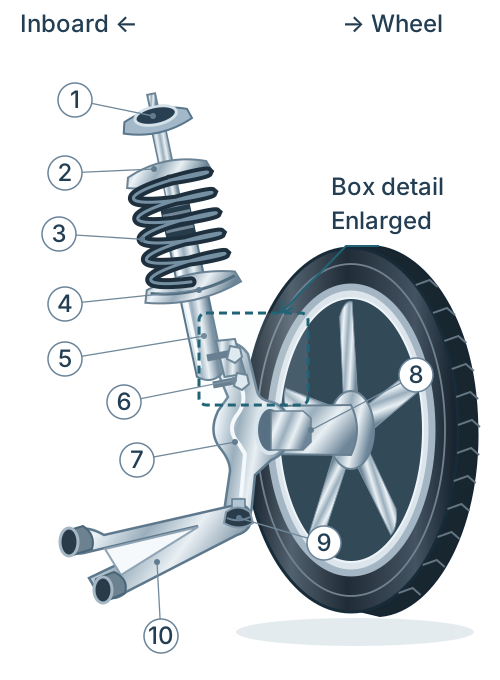
Part legend (10 items)
- Upper mounting point
- Upper spring seat
- Coil spring
- Lower spring seat
- Strut tube
- Strut-to-knuckle joint
- Steering knuckle
- Hub and bearing connection
- Lower ball joint
- Lower control arm
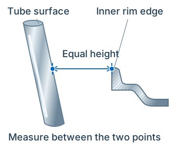
Check tyre-sidewall, spring-seat and spoke-to-caliper clearances separately.
Omitted parts and physical checks
This typical strut schematic does not reproduce actual dimensions or establish fitment. Brakes, driveshaft, tie rod, anti-roll bar and mounting brackets are omitted but also require clearance checks. Clearance changes with ride height, steering and load. Part numbers are legend references, not measurement points.
Fender positionAssessment uses a position estimated from the original size
Fender calculations use the nominal wheel-size reference. This differs from the physical rim edge; do not enter an edge measurement without checking the reference.
If a value is unknown, keep the estimate as a reference. An estimate does not establish fitment.
Estimate assumptions
From the outside of the current (original) tyre: 20mm outwards and above the upper edge by 30mm above the reference point. This is a common assumption, not a vehicle measurement.
Choose Clear fender position to disable the assessment.
View reference points and measurement locations
These fixed explanatory diagrams do not change with the inputs.
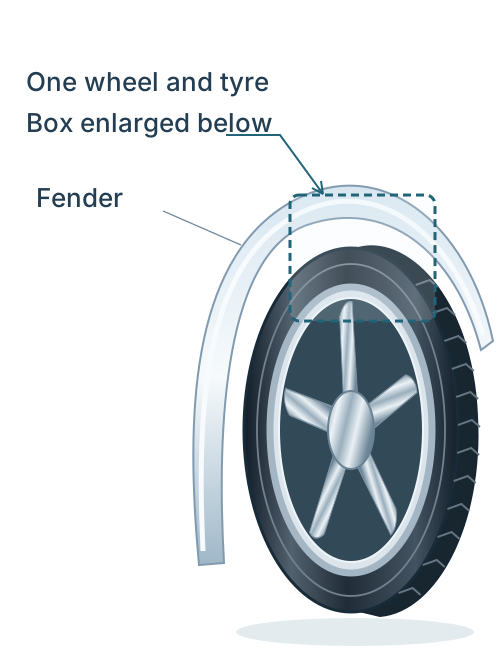
An enlarged section cuts across the wheel width. It is not simply a zoom of the same viewing angle.
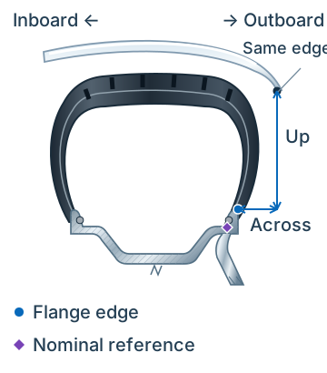
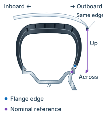
Use the distance from the purple reference. The vertical distance is between stationary points, not remaining tyre clearance while driving.
Nominal dimensions and measurement corrections
Nominal rim width is normally measured between bead seats, and nominal diameter at the tyre seat. These references can be difficult to measure on an installed wheel. Any correction from a physical edge requires product dimensions or a measured basis. No universal correction or automatic conversion is applied.
Compare candidates A, B and C Front·0/3
Keep up to three replacement candidates per axle during this page visit. Reloading or changing vehicle/specification clears them; they are not included in shared URLs or restored inputs. Use Save in My garage to keep a setup.
Candidates are recalculated against the current setup. Movement is the rim-edge difference at 0° camber, not a determination of physical clearance or fitment.
-
CandidateA
No saved comparison candidates yet.
-
CandidateB
No saved comparison candidates yet.
-
CandidateC
No saved comparison candidates yet.
Detailed results and fender assessmentDiameter, circumference, calculated speed and fender margins
Wheel position changes
- Outside (outer rim edge)
- ±0.0mm
- Outer edge unchanged
- Inside (inner rim edge)
- ±0.0mm
- Inner edge unchanged
Outer tyre sidewall ±0.0mm / inner ±0.0mm
Fender
OK- Lateral wheel margin
- 48.0mm
- Lateral tyre margin
- 20.3mm
- Difference at tyre top
- 30.3mm
Tyre diameter and speedometer
- Diameter difference
- ±0.0mm
- ±0.0%
- At an indicated 100 km/h
- 100.0km/h
- Calculated road speed
| Diameter | Circumference | Sidewall | |
|---|---|---|---|
| Current 195/65R15 | 634.5mm | 1,993.3mm | 126.8mm |
| Replacement 195/65R15 | 634.5mm | 1,993.3mm | 126.8mm |
| Indicated speed | Calculated road speed | Difference |
|---|---|---|
| 40km/h | 40.0km/h | ±0.0km/h |
| 60km/h | 60.0km/h | ±0.0km/h |
| 80km/h | 80.0km/h | ±0.0km/h |
| 100km/h | 100.0km/h | ±0.0km/h |
This assumes the speedometer is accurate with the original tyres.
HOW WE CALCULATE
How wheel offset and tyre diameter are calculated
Wheel position change
Convert rim width to mm. Without spacers, outward movement = (replacement width − current width) × 25.4 ÷ 2 − (replacement offset − current offset). A positive result means outward movement.
Tyre diameter change
Nominal diameter (mm) = rim diameter (inches) × 25.4 + tyre width (mm) × aspect ratio ÷ 100 × 2. Actual dimensions vary by manufacturer, model and condition.
This is a dimensional comparison, not a fitment determination. Check load capacity, approved rim width, brakes and suspension clearance separately.
Example: 6J / +45 to 7J / +40
Without spacers, the outer edge moves out by 17.7 mm and inner clearance decreases by 7.7 mm. Separate half the width increase (12.7 mm) from the 5 mm offset decrease. Tyre protrusion need not equal rim-edge movement.
Example: 195/65R15 to 205/55R16
Nominal diameter changes from 634.5 mm to 631.9 mm: −2.6 mm (about −0.41%). Assuming the original speedometer is accurate, an indicated 100 km/h converts to about 99.6 km/h.
Is the calculated speed a measured road speed?
Converted speed = indicated speed × replacement diameter ÷ original diameter. Original speedometer error, pressure, load, wear and rolling-circumference differences are excluded. This is not a measured road speed or a guarantee of passing shaken (Japan's vehicle inspection).
What is “shaken”? (Japan’s vehicle inspection)
Shaken (車検) is Japan’s compulsory roadworthiness inspection. A typical private car is first inspected three years after it is first registered, and every two years after that. A car without a valid shaken certificate cannot be driven on public roads in Japan.
The inspection checks that the car still meets Japan’s vehicle safety standards. For wheels and tyres, this includes whether the tyres stick out beyond the bodywork, whether the tyres have enough load capacity, and whether the speedometer still reads within the permitted range after a size change.
Shaken costs combine fixed government charges (vehicle weight tax, compulsory third-party insurance known as jibaiseki, and inspection fees) with any repair or service charges from the workshop.
This is a Japan-only system. If your car is registered in another country, follow that country’s roadworthiness and vehicle modification rules instead; this site’s pass/fail guides do not apply there.
Which axle should I enter for staggered tyres?
Compare front and rear movement and clearance separately. One axle's result is not a fitment recommendation for all four wheels. Use driven-wheel diameter for speed/RPM calculations, and check manufacturer limits for front/rear circumference differences on AWD vehicles.